top button
Flag Notify
    Connect to us
      Site Registration

Site Registration

Introduction to Sim Card and a brief about MicroSim card.

+8 votes
1,250 views

The SIM (subscriber identity module) is a fundamental component of cellular phones. It also known as an integrated circuit card (ICC), which is a microcontroller-based access module. It is a physical entity and can be either a subscriber identity module (SIM) or a universal integrated circuit card (UICC). A SIM can be removed from a cellular handset and inserted into another; it allows users to port identity, personal

enter image description here

information, and service between devices. All cell phones are expected to incorporate some type of identity module eventually, in part because of this useful property. Basically, the ICC deployed for 2G networks was called a SIM and the UICC smart card running the universal subscriber identity module(USIM) application. The UICC card accepts only 3G universal mobile telecommunications service (UMTS) commands. USIMs are enhanced versions of present-day SIMs, containing backward-compatible information. A USIM has a unique feature in that it allows one phone to have multiple numbers. If the SIM and USIM application are running on the same UICC, then they cannot be working simultaneously.

What is a microsim card?
Simply put, a Micro SIM is really just the same as a standard SIM card, just a bit smaller in size. It was developed by the European Telecommunications Standards Institute who settled on the 12 x 15mm size. So, what is its purpose? When you want to use a mobile phone you need some way of communicating which mobile network you are subscribed to. Essentially, this is what the SIM card is for: to contain network specific info that enables you to be identified by whatever mobile phone network you are signed up to. If you don’t have a SIM your phone simply will not work. You can also save lots of mobile phone contacts and other information on a SIM.
enter image description here
A regular SIM card is actually quite a large item when you consider how the current gadget world is focused on smaller and smaller scales, or more compact forms, for everything. Its size occupies a relatively large amount of internal space within the actual handset, which is often a frustration for the top designers. This is where the micro-SIM comes in. It actually made its appearance in the iPhone 4S and iPad, which are some of the thinnest gadgets seen so far in the industry. The iPhone 5 features a nano sim, what is even smaller.
What we consider today to be a conventional SIM, which we use today in normal phones, is in fact a more compact version of the credit card sized SIMs used in the old mobile bricks people carried around back in the 1990s. The micro-SIM is more like a micro micro-SIM in reality.
![enter image description here.

File System in Sim:-
A SIM card contains a processor and operating system with between 16 and 256 KB of persistent, electronically erasable, programmable read-only memory (EEPROM). It also contains RAM (random access memory) and ROM (read-only memory). RAM controls the program execution flow and the ROM controls the operating system work flow, user authentication, data encryption algorithm, and other applications. The hierarchically organized file system of a SIM resides in persistent memory and stores data as names and phone number entries, text messages, and network service settings. Depending on the phone used, some information on the SIM may coexist in the memory of the phone. Alternatively, information may reside entirely in the memory of the phone instead of available memory on the SIM.

The hierarchical file system resides in EEPROM. The file system consists of three types of files: master file(MF), dedicated files, and elementary files. The master file is the root of the file system. Dedicated files are the subordinate directories of master files. Elementary files contain various types of data, structured as either a sequence of data bytes, a sequence of fixed-size records, or a fixed set of fixed-size records used cyclically.
enter image description here

As can be seen in the above figure, dedicated files are subordinate directories under the MF, their contents and functions being defined by the GSM11.11 standards. Three are usually present: DF (DCS1800), DF (GSM), and DF (Telecom). Also present under the MF are EFs (ICCID). Subordinate to each of the DFs are supporting EFs, which contain the actual data. The EFs under DF (DCS1800) and DF (GSM) contain network-related information and the EFs under DF (Telecom) contain the service-related information.

All the files have headers, but only EFs contain data. The first byte of every header identifies the file type and the header contains the information related to the structure of the files. The body of an EF contains information related to the application. Files can be either administrative- or application-specific and access to stored data is controlled by the operating system.

posted Mar 18, 2014 by anonymous

  Promote This Article
Facebook Share Button Twitter Share Button LinkedIn Share Button


Related Articles

Customized Applications for Mobile Network Enhanced Logic (CAMEL):

CAMEL was developed as a standard for mobile intelligence across different vendor equipments for GSM network. What this means is that the end user should be able to roam between different networks (maybe in different countries) and be reachable at the same number and should receive only one bill from the original service provider (Home Operator).
The CAMEL is a network feature and not a supplementary service. It is a tool for the network operator to provide the subscribers with the operator specific services even when roaming in the another network.

Features:
The CAMEL protocol supports these mobile-calling operator-provided services: originating and terminating phone calls, charging features, prepaid minute usage, and personal subscriber options such as voice-mail prompts, recorded messages and ringtones.

Function:
The CAMEL protocol ensures that if the caller accesses another mobile operator's towers or equipment, his services remain the same as if the caller accessed his own operator's towers or equipment. And, the minutes used and the services rendered will only be billed once by the caller's own operator. This network system applies to GSM operators all over the globe.

Exceptions:
The CAMEL protocol does not apply to Emergency Setup. If a mobile user dials 911 while roaming, the CAMEL protocol is disabled. This ensures that the caller is routed to the local emergency response system and not to services in his home calling area.

Applicability of CAMEL procedures:
1. The CAMEL feature is applicable to Mobile Originated and Mobile Terminated Call Related Activities.
2. CAMEL procedures are applicable to all circuit switched basic services without distinction (except Emergency calls).
3. The CAMEL feature is applicable to Supplementary Services Invocation
4. CAMEL procedures are applicable to GPRS sessions and PDP contexts
5. CAMEL procedures are applicable to Mobile Originating/Terminating short message service through both circuit switched and packet switched serving network entities
6. CAMEL procedures are applicable to IP multimedia services (except Emergency calls) to support legacy services
7. CAMEL shall support IPMM sessions which are based on the same charging paradigm as CS/PS calls. 8. This applies most probably to VoIP and Video over IP.
9. CAMEL procedures are applicable to IP multimedia sessions addressed by either E.164 numbers or SIP URLs.

Example of CAMEL procedure:

enter image description here

Take a simple scenario of a voice call being made. When a subscriber starts to make a call, this request is received by the network's Mobile Switching Centre (MSC). The MSC then sends a message that 'queries' the SCP's database. Note that the essential element of any CAMEL solution is a Service Control Point (SCP). This unit effectively hosts a database which holds the instructions needed for an intelligent application.

The SCP processes that query, comes up with an appropriate response and then sends a message back to the MSC telling what action it should take with the subscriber’s request for a specific service. The call is then connected in the most appropriate manner, a process which is transparent to the customer. A very good example of this process in action is short code dialling over a VPN (Virtual Private Network) where the user calls a colleague’s internal extension telephone number but is, in fact, routed to that person’s mobile phone which is roaming abroad.

The main addition in CAMEL phase 2 which phase 1 omitted is support for a Specialised Resource Function (SRF) a component most often found in Voice Response Units (VRUs). For example, when an account balance reaches zero for a pre-paid customer under phase 1, the customer will simply be cut off. With phase 2 thanks to support for SRF, the customer will hear automatically generated messages from the Voice Response Unit warning that the balance is dangerously low before a call and even during the call. Naturally this leads to greater customer satisfaction.

READ MORE

With the modulation techniques development the mobile communications is being affected so much through the symbols are carrying so huge information in it.

However with this increasing technique there is also a problem called Inter-symbol interference or ISI.

Particularly in telecom ISI is a form of distortion of a signal in which a symbol interferes with other symbols. There can be multiple cause to have this ISI. It can be caused by multipath propagation or the inherent non-linear frequency response of a channel causing successive symbols to "blur" together.

Theoretically a signal receives at receiver without any loss, noise and interference but in real scenarios it does not. It will have multiple delays, multipath propagation and Band Limited channels.

Delay Spread:

A transmitted symbol can be received multiple times at the receiver, more or less as an "echo" effect. This echo is what we call "Delay Spread".

Delay Spread in ISI

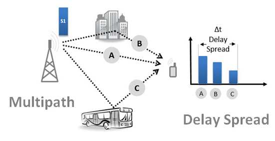
In the above figure, the transmitter transmits a single symbol. This symbol is propagated along different paths (A, B and C), and eventually reaching the receiver at multiple time instants, and therefore with multiple "replication."

The total elapsed time between the first and last is determined by the environment (including the structures, how close they are, etc..). For example, in an urban environment, where the reflection is high (many buildings, many vehicles parked and moving), this delay has a typical value of 5-10 microseconds.

Multipath Propagation:

Due to the signal propagation phenomena, like reflection or diffraction, a receiver can receive several delayed versions of the same signal. This creates Inter-Symbol Interference (ISI).

ISI in LTE

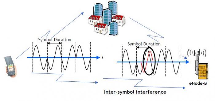
The multi-path impact is an overlapping of 2 symbols, called Inter-Symbol Interference (ISI). The modulation is based on the amplitude and on the phase, so in case of overlapping there are 2 different amplitudes and phases. The receiver is not able to decode the state of the symbol.

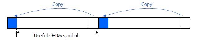
The guard time is called the Cyclic Prefix (CP). It permits to facilitate demodulation.

ISI in LTE

The cyclic prefix transforms the classical channel convolution into a cyclic convolution which permits easy demodulation after FFT.

ISI in LTE

Symbol Duration:

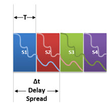
As can we easily conclude, a very important determining factor for the ISI is the time duration of the symbol.
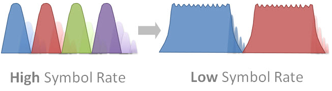
If the symbol period (T) is very short compared to the "Delay Spread" (t) the impact is significant (T << t).

Symbol in ISI

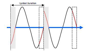
But if we can extend the symbols length, most of them will not suffer the impact of ISI (T >> t).

Symbol

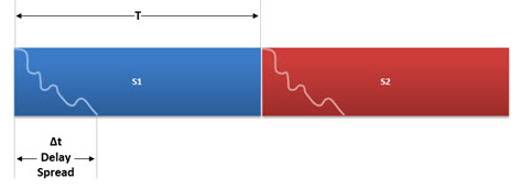
One small part of the symbol will continue to be impacted, but for most of its duration, the symbol will remain not affected by reflections propagated in "Multipath".

That is why the ISI is minimized when we use a higher symbol period (or Lower Symbol Rate).

Symbol in ISI LTE

READ MORE

In a telecommunications network, a switch is a device that channels incoming data from any of multiple input ports to the specific output port that will take the data toward its intended destination. In the traditional circuit-switched telephone network, one or more switches are used to set up a dedicated though temporary connection or circuit for an exchange between two or more parties. On an Ethernet local area network (LAN), a switch determines from the physical device (Media Access Control or MAC) address in each incoming message frame which output port to forward it to and out of. In a wide area packet-switched network such as the Internet, a switch determines from the IP address in each packet which output port to use for the next part of its trip to the intended destination.

In the Open Systems Interconnection (OSI) communications model, a switch performs the Layer 2 or Data-link layer function. That is, it simply looks at each packet or data unit and determines from a physical address (the "MAC address") which device a data unit is intended for and switches it out toward that device. However, in wide area networks such as the Internet, the destination address requires a look-up in a routing table by a device known as a router. Some newer switches also perform routing functions (Layer 3 or the Network layer functions in OSI) and are sometimes called IP switches.

On larger networks, the trip from one switch point to another in the network is called a hop. The time a switch takes to figure out where to forward a data unit is called its latency. The price paid for having the flexibility that switches provide in a network is this latency. Switches are found at the backbone and gateway levels of a network where one network connects with another and at the sub-network level where data is being forwarded close to its destination or origin. The former are often known as core switches and the latter as desktop switches.

In the simplest networks, a switch is not required for messages that are sent and received within the network. For example, a local area network may be organized in a token ring or bus arrangement in which each possible destination inspects each message and reads any message with its address.

Circuit-Switching versus Packet-Switching

A network's paths can be used exclusively for a certain duration by two or more parties and then switched for use to another set of parties. This type of "switching" is known as circuit-switching and is really a dedicated and continuously connected path for its duration. Today, an ordinary voice phone call generally uses circuit-switching.

Most data today is sent, using digital signals, over networks that use packet-switching. Using packet-switching, all network users can share the same paths at the same time and the particular route a data unit travels can be varied as conditions change. In packet-switching, a message is divided into packets, which are units of a certain number of bytes. The network addresses of the sender and of the destination are added to the packet. Each network point looks at the packet to see where to send it next. Packets in the same message may travel different routes and may not arrive in the same order that they were sent. At the destination, the packets in a message are collected and reassembled into the original message.

READ MORE
...