top button
Flag Notify
    Connect to us
      Site Registration

Site Registration

A brief introduction about telecommunication Switch

+7 votes
290 views

In a telecommunications network, a switch is a device that channels incoming data from any of multiple input ports to the specific output port that will take the data toward its intended destination. In the traditional circuit-switched telephone network, one or more switches are used to set up a dedicated though temporary connection or circuit for an exchange between two or more parties. On an Ethernet local area network (LAN), a switch determines from the physical device (Media Access Control or MAC) address in each incoming message frame which output port to forward it to and out of. In a wide area packet-switched network such as the Internet, a switch determines from the IP address in each packet which output port to use for the next part of its trip to the intended destination.

In the Open Systems Interconnection (OSI) communications model, a switch performs the Layer 2 or Data-link layer function. That is, it simply looks at each packet or data unit and determines from a physical address (the "MAC address") which device a data unit is intended for and switches it out toward that device. However, in wide area networks such as the Internet, the destination address requires a look-up in a routing table by a device known as a router. Some newer switches also perform routing functions (Layer 3 or the Network layer functions in OSI) and are sometimes called IP switches.

On larger networks, the trip from one switch point to another in the network is called a hop. The time a switch takes to figure out where to forward a data unit is called its latency. The price paid for having the flexibility that switches provide in a network is this latency. Switches are found at the backbone and gateway levels of a network where one network connects with another and at the sub-network level where data is being forwarded close to its destination or origin. The former are often known as core switches and the latter as desktop switches.

In the simplest networks, a switch is not required for messages that are sent and received within the network. For example, a local area network may be organized in a token ring or bus arrangement in which each possible destination inspects each message and reads any message with its address.

Circuit-Switching versus Packet-Switching

A network's paths can be used exclusively for a certain duration by two or more parties and then switched for use to another set of parties. This type of "switching" is known as circuit-switching and is really a dedicated and continuously connected path for its duration. Today, an ordinary voice phone call generally uses circuit-switching.

Most data today is sent, using digital signals, over networks that use packet-switching. Using packet-switching, all network users can share the same paths at the same time and the particular route a data unit travels can be varied as conditions change. In packet-switching, a message is divided into packets, which are units of a certain number of bytes. The network addresses of the sender and of the destination are added to the packet. Each network point looks at the packet to see where to send it next. Packets in the same message may travel different routes and may not arrive in the same order that they were sent. At the destination, the packets in a message are collected and reassembled into the original message.

posted Feb 25, 2014 by anonymous

  Promote This Article
Facebook Share Button Twitter Share Button LinkedIn Share Button


Related Articles

The SIM (subscriber identity module) is a fundamental component of cellular phones. It also known as an integrated circuit card (ICC), which is a microcontroller-based access module. It is a physical entity and can be either a subscriber identity module (SIM) or a universal integrated circuit card (UICC). A SIM can be removed from a cellular handset and inserted into another; it allows users to port identity, personal

enter image description here

information, and service between devices. All cell phones are expected to incorporate some type of identity module eventually, in part because of this useful property. Basically, the ICC deployed for 2G networks was called a SIM and the UICC smart card running the universal subscriber identity module(USIM) application. The UICC card accepts only 3G universal mobile telecommunications service (UMTS) commands. USIMs are enhanced versions of present-day SIMs, containing backward-compatible information. A USIM has a unique feature in that it allows one phone to have multiple numbers. If the SIM and USIM application are running on the same UICC, then they cannot be working simultaneously.

What is a microsim card?
Simply put, a Micro SIM is really just the same as a standard SIM card, just a bit smaller in size. It was developed by the European Telecommunications Standards Institute who settled on the 12 x 15mm size. So, what is its purpose? When you want to use a mobile phone you need some way of communicating which mobile network you are subscribed to. Essentially, this is what the SIM card is for: to contain network specific info that enables you to be identified by whatever mobile phone network you are signed up to. If you don’t have a SIM your phone simply will not work. You can also save lots of mobile phone contacts and other information on a SIM.
enter image description here
A regular SIM card is actually quite a large item when you consider how the current gadget world is focused on smaller and smaller scales, or more compact forms, for everything. Its size occupies a relatively large amount of internal space within the actual handset, which is often a frustration for the top designers. This is where the micro-SIM comes in. It actually made its appearance in the iPhone 4S and iPad, which are some of the thinnest gadgets seen so far in the industry. The iPhone 5 features a nano sim, what is even smaller.
What we consider today to be a conventional SIM, which we use today in normal phones, is in fact a more compact version of the credit card sized SIMs used in the old mobile bricks people carried around back in the 1990s. The micro-SIM is more like a micro micro-SIM in reality.
![enter image description here.

File System in Sim:-
A SIM card contains a processor and operating system with between 16 and 256 KB of persistent, electronically erasable, programmable read-only memory (EEPROM). It also contains RAM (random access memory) and ROM (read-only memory). RAM controls the program execution flow and the ROM controls the operating system work flow, user authentication, data encryption algorithm, and other applications. The hierarchically organized file system of a SIM resides in persistent memory and stores data as names and phone number entries, text messages, and network service settings. Depending on the phone used, some information on the SIM may coexist in the memory of the phone. Alternatively, information may reside entirely in the memory of the phone instead of available memory on the SIM.

The hierarchical file system resides in EEPROM. The file system consists of three types of files: master file(MF), dedicated files, and elementary files. The master file is the root of the file system. Dedicated files are the subordinate directories of master files. Elementary files contain various types of data, structured as either a sequence of data bytes, a sequence of fixed-size records, or a fixed set of fixed-size records used cyclically.
enter image description here

As can be seen in the above figure, dedicated files are subordinate directories under the MF, their contents and functions being defined by the GSM11.11 standards. Three are usually present: DF (DCS1800), DF (GSM), and DF (Telecom). Also present under the MF are EFs (ICCID). Subordinate to each of the DFs are supporting EFs, which contain the actual data. The EFs under DF (DCS1800) and DF (GSM) contain network-related information and the EFs under DF (Telecom) contain the service-related information.

All the files have headers, but only EFs contain data. The first byte of every header identifies the file type and the header contains the information related to the structure of the files. The body of an EF contains information related to the application. Files can be either administrative- or application-specific and access to stored data is controlled by the operating system.

READ MORE

Customized Applications for Mobile Network Enhanced Logic (CAMEL):

CAMEL was developed as a standard for mobile intelligence across different vendor equipments for GSM network. What this means is that the end user should be able to roam between different networks (maybe in different countries) and be reachable at the same number and should receive only one bill from the original service provider (Home Operator).
The CAMEL is a network feature and not a supplementary service. It is a tool for the network operator to provide the subscribers with the operator specific services even when roaming in the another network.

Features:
The CAMEL protocol supports these mobile-calling operator-provided services: originating and terminating phone calls, charging features, prepaid minute usage, and personal subscriber options such as voice-mail prompts, recorded messages and ringtones.

Function:
The CAMEL protocol ensures that if the caller accesses another mobile operator's towers or equipment, his services remain the same as if the caller accessed his own operator's towers or equipment. And, the minutes used and the services rendered will only be billed once by the caller's own operator. This network system applies to GSM operators all over the globe.

Exceptions:
The CAMEL protocol does not apply to Emergency Setup. If a mobile user dials 911 while roaming, the CAMEL protocol is disabled. This ensures that the caller is routed to the local emergency response system and not to services in his home calling area.

Applicability of CAMEL procedures:
1. The CAMEL feature is applicable to Mobile Originated and Mobile Terminated Call Related Activities.
2. CAMEL procedures are applicable to all circuit switched basic services without distinction (except Emergency calls).
3. The CAMEL feature is applicable to Supplementary Services Invocation
4. CAMEL procedures are applicable to GPRS sessions and PDP contexts
5. CAMEL procedures are applicable to Mobile Originating/Terminating short message service through both circuit switched and packet switched serving network entities
6. CAMEL procedures are applicable to IP multimedia services (except Emergency calls) to support legacy services
7. CAMEL shall support IPMM sessions which are based on the same charging paradigm as CS/PS calls. 8. This applies most probably to VoIP and Video over IP.
9. CAMEL procedures are applicable to IP multimedia sessions addressed by either E.164 numbers or SIP URLs.

Example of CAMEL procedure:

enter image description here

Take a simple scenario of a voice call being made. When a subscriber starts to make a call, this request is received by the network's Mobile Switching Centre (MSC). The MSC then sends a message that 'queries' the SCP's database. Note that the essential element of any CAMEL solution is a Service Control Point (SCP). This unit effectively hosts a database which holds the instructions needed for an intelligent application.

The SCP processes that query, comes up with an appropriate response and then sends a message back to the MSC telling what action it should take with the subscriber’s request for a specific service. The call is then connected in the most appropriate manner, a process which is transparent to the customer. A very good example of this process in action is short code dialling over a VPN (Virtual Private Network) where the user calls a colleague’s internal extension telephone number but is, in fact, routed to that person’s mobile phone which is roaming abroad.

The main addition in CAMEL phase 2 which phase 1 omitted is support for a Specialised Resource Function (SRF) a component most often found in Voice Response Units (VRUs). For example, when an account balance reaches zero for a pre-paid customer under phase 1, the customer will simply be cut off. With phase 2 thanks to support for SRF, the customer will hear automatically generated messages from the Voice Response Unit warning that the balance is dangerously low before a call and even during the call. Naturally this leads to greater customer satisfaction.

READ MORE

The LTE-based fourth-generation (4G) wireless landscape has become the new nexus where IT industry leaders from device makers to software developers to network operators are pursuing new business opportunities amid consumers demand for faster and more reliable networks. However, the concurrent mention of LTE and LTE Advanced networks in trade media may create a degree of confusion among managers who are not directly associated with LTE network technology.

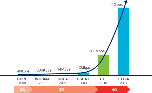
This article attempts to make a clear distinction between regular LTE and LTE Advanced wireless networks. Long Term Evolution or LTE, as the name suggests, is actually evolution of the existing 3G standard, not a new standard in its own right. In fact, LTE is simply an advanced form of 3G, also called 3.9G by the ITU. However, LTE represents a paradigm shift from hybrid voice and data networks to data-only networks. LTE offers a theoretical capacity of up to 100 Mbit/s in the downlink and 50 Mbit/s in the uplink, and more if a more powerful MIMO technique for antenna arrays is used.

LTE Advanced, like its lower-speed predecessor, is going to be built on the prior LTE OFDM/MIMO architecture to further increase data rate and is being defined in 3GPP Releases 10 and 11. The LTE Advanced standard promises more than three times data speeds than basic LTE networks. It does it by incorporating five high-octane network features: carrier aggregation, increased MIMO, coordinated multipoint transmission, heterogeneous network (HetNet) support, and relays.

LTE-Advanced

LTE Advanced Building Blocks:

First, the carrier aggregation scheme allows mobile operators to utilize more than one 20 MHz bandwidth carrier as specified in the original LTE specification, and in this way, increase the overall transmission capacity. Carrier aggregation technique combines up to five 20-MHz channels into one stream to increase data speed, making possible a peak downlink data rate of 1 Gbit/s.

Second, while the standard LTE defines MIMO configurations of up to 4x4arrangements, LTE Advanced technology extends that to 8x8 stream with support for multiple transmit antennas in the handset. MIMO is a fundamental element of the LTE system design and the first version of the LTE standard supports 2×2 MIMO in both the downlink and uplink. Subsequent developments will extend this capability, and the LTE Advanced systems will eventually support 8×8 MIMO in the downlink and 4×4 MIMO in the uplink.

Third, coordinated multipoint transmission (CoMP)—also known as cooperative MIMO—is a set of techniques that uses different forms of MIMO and beamforming to send and receive radio signals from multiple cells to a mobile device to reduce interference from other cells and ensure optimum performance at the cell edges. SK Telecom, which claims to have launched the world’s first commercial LTE Advanced network in summer 2012, actually used an early stage of coordinated multipoint to allow multiple base stations to communicate with a single device simultaneously.

Fourth, the LTE Advanced standard defines another base station type called relay station. The use of technologies such as MIMO, OFDM, and advanced error correction improves throughput, but they don’t fully mitigate the problems experienced at the cell edge. LTE relays can be used to increase the coverage outside the main area and to fill small holes in coverage.

Finally, heterogeneous network or HetNet is a multi-layered system of overlapping big and small cells which pumped out cheap bandwidth. Several small cells can be distributed within the area covered by a macrocell to provide extra capacity and fill in the gaps in cellular coverage. Mobile phone operators are very excited about moving to HetNets, which incorporate hundreds if not thousands of small cells or low-powered radio access nodes, which in turn, provide nearly the same functionality for a small region as of a larger radio base station.

Inevitably, LTE Advanced will be forward and backward compatible with basic LTE, meaning LTE handsets will work on LTE Advanced networks, and LTE Advanced handsets will work on standard LTE networks. That makes LTE a stepping stone to the much-higher-capacity LTE Advanced systems. The deployment of LTE Advanced networks is expected in 2014 and beyond.

READ MORE
...