top button
Flag Notify
    Connect to us
      Site Registration

Site Registration

An introduction to the LTE MAC Scheduler

+1 vote
528 views

LTE brought a completely new network architecture and managed to revolutionize the data capabilities ever achieved on a mobile network. LTE also brought a new type of radio network, much simpler in its organization. In a previous post we discussed about OFDM being the main reason behind LTE’s high data speed. Today we look into an essential component of the LTE radio network: the MAC Scheduler.

Sitting just above the Physical layer, the MAC Scheduler assigns bandwidth resources to user equipment and is responsible for deciding on how uplink and downlink channels are used by the eNodeB and the UEs of a cell. It also enforces the necessary Quality of Service for UE connections. QoS is a set of rules that come from the Policy and Charging Rules Function (PCRF in the core network. These rules define priority, bit rate and latency requirements for different connections to the UE. They is usually based on the types of applications using the UE connection. For example, the QoS requirements for a VoLTE call are different from those for checking the e-mail.

As seen in the image below, the MAC scheduler has control over the OFDM modulation in the sense that it decides, according to information received from other LTE network components, how much bandwidth each UE receives at any given moment. In this figure, the resource element (sub-carrier) is represented on the frequency axis, while the sub-frames are represented on the time axis.

mac_scheduler1This figure shows downlink scheduling, but the MAC Scheduler controls uplink scheduling in a similar way.

In order to take its resource allocation decisions, the MAC Scheduler receives information such as:

  • QoS data from the PCRF: minimum guaranteed bandwidth, maximum allowed bandwidth, packet loss rates, relative priority of users, etc.
  • messages from the UEs regarding the radio channel quality, the strength or weakness of the signal, etc.
  • measurements from the radio receiver regarding radio channel quality, noise and interference, etc.
  • buffer status from the upper layers about how much data is queued up waiting for transmission

mac_scheduler2

Typically, a MAC Scheduler can be programmed to support one scheduling algorithm with many parameters.

Here are some examples of scheduling algorithms:

  • Round Robin – used for testing purposes and uses equal bandwidth for all UEs without accounting for channel conditions
  • Proportional Fairness – tries to balance between the QoS priorities and total throughput, usually preferred in commercial networks
  • Scheduling for Delay-Limited Capacity –  guarantees that the MAC Scheduler will always prioritize applications with specific latency requirements
  • Maximum C/I – guarantees that the Mac Scheduler will always assign resource blocks to the UE with the best channel quality

One of the key features of LTE is the ability to control and prioritize bandwidth across users. It is the MAC scheduler that gives LTE this capability.

posted Jul 30, 2015 by Gratiela D

  Promote This Article
Facebook Share Button Twitter Share Button LinkedIn Share Button


Related Articles

GTP stands for the GPRS Tunneling Protocol and is used to encapsulate user data when passing through core network and also carries bearer specific signalling traffic between various network nodes.

Functionality Of GTP
- It provides mobility. When UE is mobile, the IP address remains same and packets are still forwarded since tunneling is provided between PGW and eNB via SGW
- Multiple tunnels (bearers) can be used by same UE to obtain different network QoS
- Main IP remains hidden so it provides security as well
- Creation, deletion and modification of tunnels in case of GTP-C

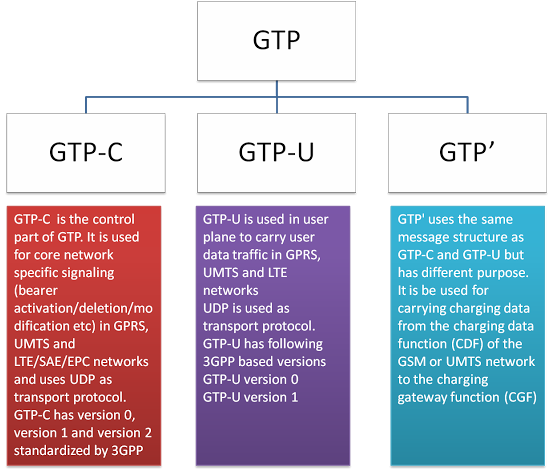
Types of GTP Protocol
Type of GTP

Various GTP Interfaces in LTE

GTP-C - Version 2
GTP-U - Version 1

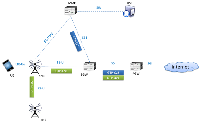
In LTE network GTP-v2 is used on S5 and S11 interfaces and GTPv1 is used on S1-U, S5, X2-U interfaces (as shown below). In inter-RAT and inter PLMN connectivity, S3, S4, S8, S10, S12 and S16 interfaces also utilize GTP protocols
GTP Interfaces

GTP-U
GTP-U encapsulation of UE user plane traffic can be understood by following example. Lets see what happens when IP packet generated by UE reaches to eNodeB and is then forwarded to SGW.

Consider any application on UE creates an IP/TCP packet. This packet consist of actual data by application, TCP or UDP header and then IP field information which has source address of UE and destination address of application server (e.g. Twitter)
GTPU

When the eNodeB receives this packet over air interface, it will put the IP packet inside GTP header which has information related to tunnel IDs. Then further, it is encapsulated inside UDP and IP header and forwarded as ethernet frame towards SGW. Here the IP header contains eNodeB IP as a source address and SGW IP as a destination address
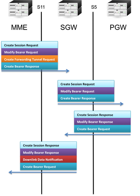
GTP-C
As GTP-Cv2 in LTE is used for tunnel management, some of the signalling messages cab be seen in the following figure -

GTP-C

GTP' (GTP prime)
GTP' uses the same message structure as GTP-C and GTP-U, but has an independent function. It can be used for carrying charging data from the charging data function (CDF) of the LTE network to the charging gateway function (CGF) over a Ga Interface.

READ MORE
...